This guide is being rewritten to update all Audio instructions for the new desk.
¶ Background
The Audio/Visual (A/V) installation at the Church is intended for audio/video display and recording/streaming as follows:-
- for internal sound reinforcement using loudspeakers;
- for providing a “Loop” output for those hard of hearing and using a compatible hearing aid (T-switch) within the Sanctuary;
- for providing video signal feeds to 3 display screens, located (2-off) at the Chancel and (1-off) at the rear wall of the Balcony;
- for providing a video/audio feed to the Display screen in the Extension Hall;
- for providing a sound feed from the Sanctuary to the Choir Room, so that the service can be heard there;
- And finally, the composite audio/video output can be recorded and/or live streamed to the Church “YouTube” channel, as either “public” broadcasts or “private” videos, either directly from the ATEM or indirectly via a PC running “OBS” software.
The system comprises a selection of up to 8 HDMI video input devices. At present these are arranged as:-
- The HDMI output from the Desk HP computer;
- Feed from a (fixed) Camcorder at the LH side of the balcony (labelled Camera 1 – CAM1)
- The fixed zoom camera at the middle of the balcony (CAM2);
- The PTZ (Pan/Tilt/Zoom) camera at the RH side of the balcony (CAM3);
- The HDMI feed from the Chancel;
- The HDMI socket at the desk area.
Channels 7 & 8 are currently unused.
The Video Mixer (Blackmagic Design ATEM Mini Extreme) is used to direct video output to the 3 display screens in the Sanctuary, and then a relay screen in the Extension Hall. The video mixer also drives a Multi-view display monitor – the LH display on the desk. This display monitor shows all six inputs, the incoming audio levels, livestream/recording status, and a Preview (Green) and Program (Red) feed.
A link between the Sound Desk and the Video Mixer provides an audio/video feed to the Video mixer.
The composite video output from the ATEM is directed to the Router via Ethernet and also to a recording channel (as MP4) on USB-C Port 1. USB-C Port 2 is used for a Video feed to the PC for OBS Studio - which then goes onto YouTube for live transmission.
A PC (HP EliteDesk 800 G3 SFF) is mounted under the desk, and uses the RH Monitor on the desk. This PC is used to set up and control the live stream software (YouTube Studio) and to provide a video feed to the Vision Mixer from e.g. a Powerpoint display and/or embedded videos in Powerpoint displays. Audio from such videos is directed from the PC to the sound desk (Input 21/22) and thence to the Vision Mixer. Note that for this to work the PC audio output must be set to Speakers and NOT to BMD composite audio.
¶ Audio
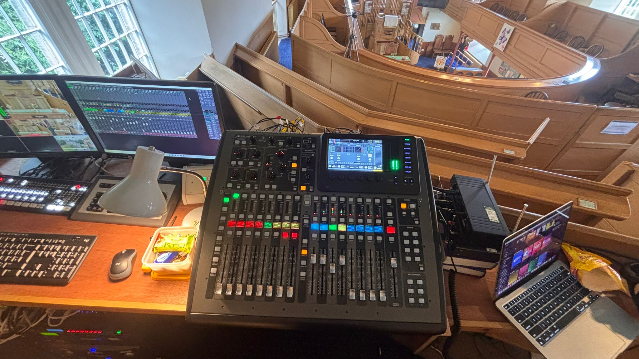
The audio system comprises a Sound Desk (Behringer X32 Compact) which has facilities for 16 (XLR) microphone and 8 other jack inputs, which may be single (mono) or stereo.
Inputs to the mixer (note this is different than on the Channel Strips) have been set up in a left to right progression, to mirror the location of microphone (and other input sources) throughout the Sanctuary.
Channel strips are layed out in layers of 8, with two banks of 8 available for display. By default, Ch1-8 is displayed on the first bank of 8 and Group DCA 1-8 is displayed on the second. This can be changed to any combination you wish. To extend channels across the full 16 strips over the two banks, press down any two channel layer buttons at once.
Microphone inputs (XLR balanced) have been set up as follows:-
| Desk Input (IN*) | Port ID | Usage |
|---|---|---|
| 1 | BL1 | Congregation Mic Left |
| 2 | BL2 | Congregation Mic Centre |
| 3 | CL1 | Choir Alto |
| 4 | CL2 | Choir Soprano |
| 5 | CL3 | Choir Bass |
| 6 | CL4 | Spare Input |
| 7 | PUL | Organ Close-pickup |
| 8 | BR1 | Congregation Mic Right |
| 9 | BR2 | Spare Input |
| 10 | CR1 | Clavinova Direct Injection (DI) |
| 11 | CR2 | Lectern Mic |
| 12 | CR3 | Spare Input |
| 13 | CR4 | Spare Input |
| 14 | Desk | Radio 1 (Sennheiser ew100 G2) |
| 15 | Desk | Radio 3 (ProSound Red) |
| 16 | Desk | Radio 4 (ProSound Yellow) |
AUX inputs have been setup as follows:-
| Desk Input | Usage |
|---|---|
| AUX 1 | Rode GO Mics Left |
| AUX 2 | Rode GO Mics Right |
| AUX 3 | Laptop / Phone Input Left |
| AUX 4 | Laptop / Phone Input Right |
| AUX 5 | PC Left |
| AUX 6 | PC Right |
For normal use, the channels have been allocated as follows (and as shown on the Strips):-
| Channel ID | Channel Name | Source | Layer | DCA Grp | Mute Grp |
|---|---|---|---|---|---|
| 1 | Radio 1 | IN14 | 1 | N/A | N/A |
| 2 | Radio 2 | AUX2 | 1 | N/A | N/A |
| 3 | Radio 3 | IN15 | 1 | N/A | N/A |
| 4 | Radio 4 | IN16 | 1 | N/A | N/A |
| 5 | Lectern | IN11 | 1 | N/A | N/A |
| 6 | Blank | N/A | 1 | N/A | N/A |
| 7 | PC L | AUX5 | 1 | N/A | N/A |
| 8 | PC R | AUX6 | 1 | N/A | N/A |
| 9 | Cong Left | IN1 | 2 | 1 | 2, 3 |
| 10 | Cong Centre | IN2 | 2 | 1 | 2, 3 |
| 11 | Cong Right | IN8 | 2 | 1 | 2, 3 |
| 12 | Choir Alto | IN3 | 2 | 2 | 1, 3 |
| 13 | Choir Bass | IN5 | 2 | 2 | 1, 3 |
| 14 | Choir Soprano | IN4 | 2 | 2 | 1, 3 |
| 15 | Clavinova | IN10 | 3 | N/A | N/A |
| 16 | Organ | IN7 | 3 | N/A | N/A |
| 17 - 30 | Assigned to Stagebox | AES50 A | 3/4 | NA | NA |
| 31 | Rode GO II | AUX 1 | 4 | N/A | N/A |
| 32 | Rode GO II | AUX 2 | 4 | N/A | N/A |
Those with further training may opt to connect an S16 Stagebox into Input A (AES550) for another 16 channels of XLR input and another 8 channels of XLR output. These channels, plus the four "Spare Input" XLR channels on the Analog lines can be patched into Channels 17-24, 25-32 on the last two layers of the desk.
Outputs from the desk go to the Sanctuary loudspeakers via the Main Mix in Stereo, routed to the Behringer speaker control unit (in turn feeding the 3 stereo power amplifiers for the Sanctuary speakers), to the Livestream (MixBus 1/2 stereo) via a Stereo Matrix (L/R) to headphones for monitoring the desk output; to the Loop amplifier (MixBus 4); and to the amplifier/speakers in the Choir Room (Straight tap-off from the Stereo Livestream Matrix Left channel).
The Master L/R XLR outputs are routed to the Sanctuary speakers.
Audio output from the desk PC is directed to Input AUX5/6 & Channels 7/8 on the Mixing Desk.
¶ Video
The following diagrams show the location of the various components of the A/V system. Refer to keys below. 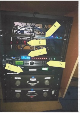
A. SySystems HDBaseT switch
B. 3-off SDI to HDMI converters (for cameras)
C. Adastra Sequential Power Control
D. Behringer Speaker Controller
E. Power amplifiers; top=downstairs rear; middle=Upstairs; bottom=downstairs front
The video installation was installed in December 2019 and substantially revised in December 2022, and provides basic facilities for video feeds to two large (LG70UU640C) 70” displays at the Chancel and a (LG49LV340C) 49” display at the Balcony facing the Chancel.
The system has been set up for future expansion which can include an additional Pan/Tilt/Zoom (PTZ) camera to be installed at the LHS of the Balcony.
The system provides live feeds from three cameras, the first being a fixed view (with zoom) camcorder at the balcony connected via a 10m HDMI cable (this runs under the carpet and into the area underneath the AV Desk) (Input 2 on the ATEM) (Panasonic HC-V770), then another fixed view (with zoom) camera (PTZoptics PT12X-ZCAM) focussed on the whole chancel (Input 3 on the ATEM), and a second PTZ camera (PTZoptics P20X-SDI-GY-G2) located to the rear right side of the balcony and able to view most areas of the Chancel (especially the location of the font for Baptismal services (Input 4 on the ATEM).
The cameras are controlled by a joystick controller (PTZoptics PT-JOY-G3) mounted at the Control Desk.
A fourth camera feed can be set up using the floor box on the Chancel, which is connected to Input 5 of the ATEM.
Using a standard HDMI interconnect cable limits the camera to within about 8m of the floor box, but 20m and 30m HDMI over fibre-optic reels are available which can be used to enable a camcorder to be used outside the Choir Room entrance.
If using the audio feed from this camera, the audio gain on Input 4 of the ATEM should be set to about -20dB and switching set to “AFV On”.
Additional video feeds to the system can come from a laptop or tablet computer located on the Chancel (a floor-mounted box which provides an HDMI connection and two 240V power sockets) and/or at the Control Desk (with HDMI or mini-Display Port connections).
The fibre-optic reels are stored at The Cornerstone but can also be used in connections directly into the ATEM. Previous setups include drops from windows at the Chancel area.
The under-desk PC is set up to provide a video feed to Input 1 of the Blackmagic Design ATEM Mini Extreme. All video inputs to the ATEM are HDMI and currently running at 1080p (1920x1080 landscape canvas) resolution with 60 frames per second (fps).
¶ Video Desk
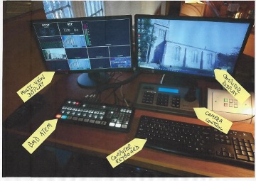
- Video “Multiview”
- Under-desk PC Display
- ATEM Video Mixer
- Camera controller
- PC keyboard and mouse
The discrete camera feeds are directed to a Vision Mixer unit (BlackMagic Devices ATEM Mini Extreme) located on the desk. An audio feed from the Sound Desk is also routed to the Microphone 1 input of this unit for recording purposes. The outputs from the Vision Mixer comprise a feed to a Multi-View monitor (IlYama E2280HS-B1) with split screens views of the feed on all 8 channels of the Mixer. The Multi-view also includes information displays on the two recording channels and the Live-Stream channel.
The Vision Mixer is used to determine which of the various input feeds is moved to the Main Program output.
Control of the various camera features (pan/tilt/zoom/focus etc.) is provided by a joystick control. This control also provides for a number of presets for each camera, which can be recalled from the joystick panel.
The joystick operation can be “Locked” by holding down the “Esc” key on the keypad for 3 seconds (approx.) to prevent inadvertent movements.
It is unlocked by repeating the Esc key routine.
On/Off control of the screens is managed by a 6-way switch on the Control Desk. The other 4 switch options on this unit are not enabled for any purpose.
Power to the various sets of equipment is controlled by switches beneath the Control Desk. This is supplied by (within the Plant Room) a separate power distribution panel (with RCD). This will provide power to two double sockets (on the LHS) which are permanently on, and provide power to the Networking Infrastructure (which is linked back to The Cornerstone) and via the Fused Spur unit (5A fuse) to (on the RHS of the Fused Spur):-
- The Sound desk (Behringer X32 Compact);
- The ProSound radio microphone receiver
- The Sennheiser radio microphone receiver
- The Trantec radio microphone receiver
- A generic AA battery charger
- 8-way AA battery charger
- The A/V PC (under the desk); and the associated
- Power to the A/V rack (the sequential control will power up);
- A surge-protected multi-way extender supplying the loop amplifier, the two video monitors and the HDBaseT link between the Extension Hall and the A/V desk.
The equipment in the A/V rack can now be powered up from the Adastra PDU (power distribution unit). This unit ensures that the various items of equipment are switched on in a sequence that minimises possible “spike” damage to equipment. The unit also monitors incoming supply voltage and will provide an audible warning of over-voltage and shutdown protection for severe over-voltage (currently set at 255V) .
This will power up
- The three power amplifiers (in sequence);
- The speaker controller;
- The vision mixer;
- The final vision mixer display
Cameras are on 24/7 as they are connected to the core Networking Infrastructure.
¶ Basic Operation
¶ Start Up
Power is supplied from a distribution box in the plant room. This has an earth leakage device, which sometimes trips for no apparent reason! Power is permanently supplied to the 3 Video screens and to the desk area, with power permanently on to the Heating Controller and the Networking Infrastructure.
The system has been set up to be switched off and on using the Fused Spur switch in the socket bank below the wooden desk.
Once you turn on the Fused Spur, you should turn on the Sound Desk via the On/Off switch at the back.
Once the Sound Desk is powered up (all LEDs illuminated & screen displaying channel strip settings), Powering up the equipment rack is undertaken by pressing the “On” button of the Adastra Sequential Power control, which will switch on all the remaining equipment.
The audio system has been set up by default for a “normal” service using one or two radio microphones and the Lectern microphone. Other microphones have been set up for recording purposes but are not active for the Sanctuary sound reinforcement. The Loop Amplifier (for hearing aids) and the feed to the Choir Room are also enabled by default.
Please check that the “mute” buttons on the Lectern and the first two Radio microphone channels have not been set (red light will be off if this is the case).
It is NOT recommended that the system be used for anything other than audio reinforcement, unless one of the IT Committee is present to operate the equipment. The sound desk will be left with channels enabled to ensure that this is possible, i.e. with Radio Mics 1 & 2 and the Lectern Mic enabled.
¶ Setting up the Sound Desk for small events
soon.
¶ Shutting down.
Shut down the system in the reverse order to switching it on.
You must turn off the Sound Desk by hitting the "Setup" button, and then hitting "ShutDown" using the first dial to the left underneath the Large LCD screen. Failure to do so will break the desk.
¶ Advanced Operation
¶ Audio -- REWRITE
¶ Behringer X32 Compact
¶ Input devices
There are 16 mono/mic input channels to the desk, these being single microphone (XLR plug). There are another 6 1/4" jack inputs (AUX In's) or 4 1/4" jack inputs & 1 RCA phono input. These can be linked into a stereo pair (1/2, 3/4 etc.)
- Microphones:-
We have 4 types of microphone as follows:-
a. Beltpack radio microphones (2 off). We have three beltpacks, the Sennheiser ew100 G2 (Radio 1), Trantec S4.4 beltpack (Radio 2), ProSound beltpack (Radio 4). There are two headsets & three Lapel microphones. Preferrably, a headset microphone should always be used, although a Lapel can also be put onto the beltpack by removing the headset jack and inserting that of the Lapel. If wearing a headset, it should be around 10cm from the mouth - not directly in front. If wearing a lapel microphone, it should not be covered by clothing and should be clipped as close to the mouth as possible.
b. Rode Radio microphones (2 off) . These comprise a wearer pack (battery powered, 2xAA rechargeable) coupled wirelessly to a receiver (Channels 8 & 9, Radio 1 and Radio 2). The signal output from these is quite high and should go into the relevant “Line” input. Take care when using the lapel microphone that it is as close as possible to the mouth and is not covered by clothing. Similarly, if using the “headset” mic, be careful to ensure that the boom microphone is at the side of the mouth rather than in front of it.
c. Condenser microphones (Audio Technica AT2020 and PRO45, AKG C1000S mics and Electro-Voice Lectern mic, and Behringer HM50). These are plugged into the XLR inputs, but require “phantom” power from the desk. These microphones have a “cardioid” response pattern with the exception of the EV lectern mic, which is interchangeable between Cardioid, SuperCardioid, HyperCardioid & Omnidirectional - currently this is set at SuperCardioid and it is highly advised not to change this!
d. Dynamic microphones. These also go into the XLR inputs, tend to be cardioid and do not require phantom power. We also have 2-off Shure SM58 and 2-off Shure SM57 dynamic cardioid microphones which are best used for vocals. - Other input devices:-
We have other forms of input to the desk as follows:-
a. An adapter (DI Box typically Behringer Ultra DI) that can convert the Line output from the Clavinova (underneath the keyboard and marked Line Output L/R) to a balanced microphone output (Digital Piano socket and input section) – this can be used for any high level sound source e.g. electric guitar;
b. Feeds from a playback system (radio, CD player etc.) can be routed to the 2 RCA plugs (L/R) on AUX5/6 , or to the ¼” L/R jacks on Channel 19/20. Take care not to overload the input channel;
c. An audio feed from the PC audio output, which is used to play audio from video feeds to the Video mixer, or indeed any other audio feed as required from any of:
- The DVD drive on the computer;
- A USB device plugged into the computer; or
- Any audio file on either the PC hard drive or accessible from the network drives or internet.
Please note that there may be more devices needing inputs than there are inputs – selection may be required!
¶ Setup Schemes
A number of console setup schemes have been compiled for typical sound console uses likely to be encountered. These will be developed over time. It is recommended that the scheme be developed and recorded using the template, which provides for a labelling attachment for the desk.
¶ Setting up input channels
--NEW IMAGE HERE--
1 – Combined Mic (XLR mono), line level jack (top-stereo, use both for individual L/R jacks) input to channel 7/8 and 9/10).
2 – USB 12-channel output. 2xRCA inputs to Channel 11/12 above.
3 – AUX 1 controls (Speakers). Individual channels to left with master control at RHS with pre-post fade switch and PFT switch.
4 – AUX2 controls (Loop amplifier). Functions broadly as AUX1 above.
4.1 - AUX3 controls (Choir Room speakers). Similar functions as first two AUX buses.
5 – individual channel “Pan” controls (L/R balance)
6 – Mute button and indicator (per channel).
7 – Group 1&2 master faders – currently unused.
8 – Individual channel main mix fader
9 – Master mix fader (record output)
To set up an input channel, the relevant channel should have its fader and Auxiliary outputs (Aux 1 & 2) set to minimum and the channel set to “PFT”. The channel gain should be increased until the individual “clip” red LED starts to illuminate and the Main Meters show peak levels of about +6dB when the sound at the input is at a maximum (shouty!)
Once this is complete, un-set the “PFT” switch on the channel. The channel can then be “mixed” into the main mix (to headphones monitor and record channel) by using the channel fader as necessary, to achieve a satisfactory balance of all the channels.
The sound levels directed to the Sanctuary speakers should then be adjusted using the Aux 1 channel gain control and the Aux 1 Master control (this latter should normally be left at about 1 o’clock).
NOTE THAT THE AUX1 PRE-POST FADE BUTTON MUST BE SET TO PRE-FADE.
If the channel is from a microphone in the Sanctuary (Radio Mics and Lectern mic most commonly), gradually increase the Aux 1 channel gain control until feedback just starts, then back off a bit.
In practice, there is little need to direct any other channel than the two radio mics and the Lectern mic to the Sanctuary, as the system is there primarily for speech reinforcement.
Similarly, the feed to the Loop Amplifier should be taken mostly from the speech channels (Radio 1 & 2, Lectern mic). Ensure that the loop amplifier is not being overloaded by adjusting the Aux 2 Master control. The green LED on the Loop amplifier should be showing flickering green but the “Limiter” red LED should not be going red for any prolonged period. Once set up, there should be no need to make further adjustments.
Note that the mixed outputs of either Aux 1 or Aux 2 can be audibly checked through the headphones by using the relevant Aux 1 or Aux 2 “PFT” switches (when headphones are plugged into the desk).
Once set up as above, it should not be necessary to adjust the individual channel gain, unless the input device (microphone or other) is changed, or the microphone location is changed.
¶ Mixing Channels
¶ Recording Mix
Channels to be included in the Recording mix are selected by using the Master “MST” channel pushbutton. This directs the channel post-fader output to the Master bus.
In practice, almost all channels will be selected, since they all serve a purpose in the mix.
The feed to the mixed output (USB Master L/R) is controlled by the Master Fader, which also controls output to the Level Meters (L/R) and also the Headphones (unless a “PFT” switch is active).
The level of individual channels to be put into the mix is controlled by the individual channel faders. Note however that the Channel “Mute” button mutes ALL outputs from the channel – use with care!
With most channels active and the Master fader at about 0dB, the Master Meter should be showing output levels of about -12dB to -3dB (occasional excursions to +3dB are acceptable, and these levels should provide satisfactory recording levels through the USB connection).
¶ Aux 1 Mix (Sanctuary Speakers)
There should be little need to make any adjustments to the mix to the Sanctuary speakers. Overall levels can be increased (if the Sanctuary is very busy) or decreased using the Aux1 Master control. The balance between Radio mics, the Lectern mic, the feed from PC playback (Ch 21/22) and any connected Bluetooth device (Ch 19/20) can be adjusted using the individual Aux1 channel controls, though care should be taken to avoid feedback. Use of these controls will NOT affect the Recording Mix.
¶ Aux 2 Mix (Loop Amplifier)
The Loop Amplifier should be set up in much the same way as Aux1. The Aux2 Master control should be used to ensure that the amplifier is not over-driven (the red clip light should only very rarely show). As with Aux1, there should be little need to make adjustments.
¶ Aux 3 Mix (Choir Room)
The mix to the Rear Hall amplifier is a mono feed taken from the Auxiliary 3 output.
The feed should be set up in the same way as Aux 2.
¶ Line Input for Playback purposes
Cables have been provided with a 3.5mm stereo mini-jack (can be used on phone or player headphone outputs or computer sound card outputs). This is connected into any of the the 15/16, 17/18 or 19/20 channels using left and right ¼” TRS jacks, or into the 21/22 channel using RCA L/R jacks.
Unlike the Mono channels (1-14), these channels are basically stereo channels, but with the option of a single mono XLR input, or single mono inputs (Left or Right) or dual stereo inputs. The single fader is in effect a stereo fader, with the “PAN” control favouring L/R balance.
Setting up the channel and player for use is completed in the same way as above for microphones etc., using the “PFL” button to check for a reasonable input level, and the various mix faders for the distribution to Sanctuary / Choir Room / Recording as considered necessary.
¶ Recording from the Desk to a recording device
Two output formats for recording have been provided. The preferred method is through the Desk’s USB output port, which can provide a 24-track output to a suitable recording device (DAW). The alternative feed uses the XLR outputs from the Master fader; this is currently routed to the Vision Mixer for embedding into a composite video/audio feed to a recording device and/or live streaming.
We have two software's available for this - Audacity & REAPER - both of which you can find guides for recording with by pressing on the name of the software you wish to use.
¶ Video
¶ Input Devices
The system has been set up with provision for 8 input devices, these being:-
- The under-desk PC, set up as Input 1 (“Desk PC”) on the ATEM. This feed works as an extended screen (another screen) to the existing main display monitor.
- An HDMI feed from a static camcorder as a replacement for a second PTZ camera, to be installed at a later date. This is to be located at the rear LHS of the balcony and cabling has been provided for this, terminating as a spare HDMI connection at the ATEM. Cost limitations on the initial installation (as well as function overload!) have meant that this is an upgrade for later. Its function would be to provide video coverage of the Sanctuary similar to that provided by the RHS camera, but covering the other side of the Sanctuary e.g. Readers at the Lectern, Communion Elders, etc. The static camcorder should be setup on the Lectern or in another position as/when required. This is setup as Input 2 ("Camera 1")
- An HDMI feed from the fixed-direction camera (Zoom only) mounted on the rear balcony wall, just beneath the rear screen. This is a video-only feed. This is currently set up as Input 3 (“Camera 2”) on the ATEM.
- An HDMI feed from the Pan-Tilt-Zoom (PTZ) camera located on the rear RHS of the balcony. This also is a video-only feed, and is currently set up as Input 4 (“Camera 3”) on the ATEM. It can be used to cover most parts of the Chancel area with the ability to zoom in on (for example) the Font during Baptisms or the Lectern during Readings.
- An HDMI feed from the Chancel (floor box containing 2-off 13A power sockets and 1-off HDMI socket), set up as input 5 (“Chancel”). An extension cable has been provided for the HDMI cable to extend to about 5m. Adapters can be used, as above.
PLEASE NOTE – if this extension is used, there should be some means employed to prevent trips on trailing cables (which damage both people and equipment!).
NOTE:- this feed will provide composite video/audio, but there is currently no way to extract the audio for routing into the Sanctuary via the sound desk. If audio is required, it is best to run the whole video from the desk PC.
- An HDMI socket on the desk, set up as input 6 (“Camera 6”) which can be used to connect to another composite video playback device such as a laptop, tablet, camcorder etc with an HDMI feed.
- An HDMI socket on the desk, set up as input 7 (“Camera 7”) which can be used to connect to another composite video playback device such as a laptop, tablet, camcorder etc with an HDMI feed.
- An HDMI socket on the desk, set up as input 8 (“Camera 8”) which can be used to connect to another composite video playback device such as a laptop, tablet, camcorder etc with an HDMI feed.
Any of these input feeds (indeed, any spare channel on the ATEM) can be used to connect a portable video camera (e.g. the Panasonic), providing a clean composite video output.
Composite feeds (e.g. videos) including sound may require that the ATEM audio switch on the channel is activated (AFV light illuminated), and the channel Gain control has been adjusted suitably. The audio will only be channelled to the program output (master) when the feed is selected and active as master. If the “ON” button is selected, the audio feed will go to the master output regardless of the channel selection. However, it must be remembered that audio brought in this way will NOT be broadcast within the Sanctuary or carried onto the audio recording mix!
All the available feeds to the Vision Mixer will appear on the Multi-view monitor on the Control Desk. The screen on this monitor is split into 13 frames, the large frame being the “Program” screen (RH Upper). 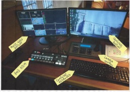
The lower 8 frames on the Multi-view Monitor will show all the available feeds to the ATEM.
The two small frames above show respectively an audio mixer panel (LH side) and a Preview screen (“Next”). This preview screen shows the channel selected for next display by “Cut” or “Auto” transfer.
¶ Switching video inputs to Program
The ATEM has 8 pre-selection buttons (labelled 1-8 to match the inputs). The currently selected input “on-air” (i.e. going to the “Program” displays on the LH monitor, the screens, and (if active) the Live Stream and/or Record) will be illuminated RED.
The “Preview” input (which can be any of the remaining 7 inputs) will be illuminated GREEN, and will appear on the “Next” frame of the LH Monitor. NOTE – there can be only ONE green button showing; they will not “stack up”!
Switching between the “Program” feed and the “Preview” feed (as shown on the LH Monitor) is accomplished by pressing either the “Cut” or the “Auto” buttons on the ATEM.
The “Cut” button does what it says on the tin! – an immediate cut from the Program view to the Preview view, while the “Auto” button will use whatever fade/mix setup has been programmed (the default is a gradual – about 1 second – transition. )
This facility can be easily used to transition from a Camera feed to a Worship presentation, as – unless changed – the Vision Mixer will simply cycle between the Preview and Program feeds.
However, if other feeds are wanted – e.g. pre-set views from the camera(s), - then these “next” previews will need to be set up on the ATEM by using the appropriate Input Channel selector (which will light up green).
¶ Media Player feeds.
Two further channels (MP1 and MP2) are available on the ATEM. These have been set up as
- MP1 is a blank church logo - and is presently used as the Church Logo at the bottom right of the screen each week.
- MP2 is an image of the church, which can also be used if an incident ever occured in the Church where the livestream had to be momentarily cut (in this instance the audio input should also be turned off entirely)
¶ Camera set-up and Pre-sets.
As installed, we have two “fixed” cameras.
- Camera 2 is a fixed position variable zoom camera focused on the Chancel. The zoom allows for a full-width view of the Chancel up to a close-up of the centre of the Chancel including the Pulpit. This view (Cam 2 on the LH monitor) is especially useful for the Control Desk operator(s) as it covers parts of the Chancel that cannot be normally seen from the Control Desk location.
- Camera 3 is a Pan-Tilt-Zoom camera. Its default position (on switch-on) is to look across the Sanctuary – not helpful! To be effective therefore it will always have to be set up for use, either by using the manual controls or by enabling a pre-set.
Provision of equipment capacity and cabling has been made for the future installation of a second PTZ camera on the other side of the Sanctuary.
The cameras are controlled from the Joystick control pad on the Control Desk. The display shows which camera has been selected. Switching is done from the LH button stack showing “CAM1” to “CAM6”. 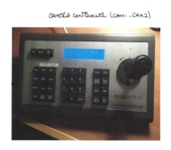
Whenever one of the available cameras (2 or 3 at present) has been selected, the Joystick control can be used to “Zoom” (twist right to zoom in, left to zoom out), or additionally (for Camera 3 only) “Pan” left (push left) or right (push right), and “Tilt” forwards to go up and backwards to go down (Note – the console will show which way has been selected).
This can be done while the Camera is “on-air” but is NOT recommended unless necessary!
It will always be better to make any adjustments while the Camera is either on the Preview pane or is showing only on the available inputs frames, because the movement rates are (at present anyway) rather rapid.
The camera control panel also provides a feature where views (per camera) can be stored as pre-sets and called up later as required.
To Preset views:-
- Ensure the correct camera has been selected (LH buttons CAM2 or CAM3 and check display);
- Set up the required view using the zoom/pan/tilt (as available);
- Press “Set” (LH button pad);
- Press a numeric number (middle keypad) – you can over-write previous settings;
- Press “Enter” (middle keypad).
To Recall a preset view:-
- Ensure the correct camera has been selected (as above);
- Press “Recall” (LH Button pad):
- Press the number pad for the chosen preset – it will probably be best to have set up a note of the pre-sets already made! Notes of presets stored have been recorded on the whiteboard.
- Press “Enter” (middle keypad).
- Check on the LH Monitor that the camera has moved to the expected view (if not, panic, or start again! – it may be necessary to press the “Esc” button to clear earlier commands)
The RH keypad has a number of other controls, not presently used. At present, both cameras are set by default to “auto-focus” which works well. They can be manually focussed but the controls seem to be very abrupt!
¶ Camera Presets List
| Camera | Preset No | Location |
|---|---|---|
| Cam 1 | NO PRESETS AVAILABLE | |
| Cam 2 | 1 | Far out view |
| Cam 2 | 2 | Mid out view |
| Cam 2 | 3 | Table |
| Cam 3 | 1 | Choir |
| Cam 3 | 2 | Table |
| Cam 3 | 3 | Pulpit |
| Cam 3 | 4 | Lectern |
| Cam 3 | 5 | Bible Entry/Exit |
¶ Audio inputs to and outputs from the Video system.
HDMI inputs to the video system can carry audio signals. This audio will be mixed in the ATEM onto the Program output – but will not be available for routing into the Sanctuary audio system, the Loop amplifier or the Rear Hall speakers, as the audio injection point is downstream of the sound desk.
In practice, an audio feed from a composite video will either be derived from the audio output of the Desk PC (to Ch 21/22) or from an audio feed from a chancel PC/laptop/tablet connected by Bluetooth to the sound desk (Ch 19/20).
¶ Recording the composite video
The ATEM unit provides for two recording devices (USB-C connections) to be run simultaneously.
In general use, we use one of the channels connecting to an extender/adapter cable suitable for a USB2.0 type A device.
When a suitable drive is connected, a green light appears at the Record button location on the ATEM. Recording is then started and stopped using the ON button on the ATEM. Plugging/unplugging of flash drives should only be undertaken when the unit has been powered down.
Recordings are in MP4 format and generally labelled as “Untitled xx” where xx is a sequential number. These can be loaded onto Audacity (for audio file extraction and editing) or Filmora (for video files editing).
¶ Streaming composite video
Separate instructions for setting up and running livestream services have been compiled, see here
¶ User Manuals and other information.
Hard copies of User Manuals have been collected into a Pocket File Folder, and are kept at the Control Desk in the filing cabinet. “Soft” copies have been distributed to relevant users, with masters kept on the Google Drive Audio Visual site. Hypertext links have been used throughout these Instructions to link to the various manuals (this only works if being viewed on the Google Drive folder, which is available on the desk PC).
The filing cabinet at the Control Desk is also used to store various hardware items, such as microphone cables, microphones, stand adapters, connecting cables and other system interconnect devices, although the majority of devices are now stored in The Lab at The Cornerstone.
Radio microphones are kept in the camera bag, along with the “AA” battery charger and batteries.
All power to the A/V Equipment is from a separate Distribution Board in the Church Plant Room, which serves to isolate it from spikes etc. arising from other connected equipment in the Church. This is an RCD-protected distribution board. The three individual circuit breakers have been marked to show which circuits they control.
¶ Amendments. (remove?)
V2.0 September 2020 – Original.
V2.1 May 2021 – minor amendments to reflect audio routings from Video Mixer.
V2.2 October 2021 – amendments to add more illustrations and revised audio routings.
V2.3 July 2022 – amendments to account for Desk PC and other adaptations.
V3.0 December 2022 – revision following changeout of TV Studio and Datavideo
V3.1 November 2023 – revision following installation of Signature 22MTK desk.
V4 August 2025 - revision following installation of Behringer X32 Compact sound desk.
V4.1 January 2026 - further revision of audio instructions following settled use of Behringer X32 Compact.